The Pico has internal pull up /down circuits inside it.
I have made this simple circuit for demonstration.
Schematic showing LED connected to GP4 and a Button connected to GP22
Button could be connected in two ways.
Internal Pull Up/Down
External Pull UP/Down
In the schematic i connected a button to GP22 using a external pull up of resistor 10k. I also used a capacitor in parallel with the button to debounce the button externally.
Using a external pull-up resistor can also help to protect the GPIO pin from damage due to excessive current flow. Without a pull-up resistor, a short circuit or other electrical fault in the switch or button could potentially allow a large current to flow through the GPIO pin, damaging it or the microcontroller itself.
Sample Code
import machine

# Set up the button on GPIO22 with external pull-up resistor
button = machine.Pin(22, machine.Pin.IN, machine.Pin.PULL_UP)

# Set up the LED on GPIO4
led = machine.Pin(4, machine.Pin.OUT)

# Loop forever
while True:
    # Read the current button value
    curr_button = button.value()

    # If the button is pressed, turn on the LED
    if curr_button == 0:
        led.value(1)
    # Otherwise, turn off the LED
    else:
        led.value(0)
The internal temperature sensor of RP2040 is read using micropython. The Thonny IDE is used in Windows environment.
The temperature sensor is connected to Channel number 4 of the ADC.
But since this is a rather small implementation using Thonny IDE, it does most of the interfacing related code in the background.
Code
import machine
import time

"""
Function Name: Read internal temperature sensor
Description: This function reads the internal temperature sensor of RP2040 chip.
             The temperature sensor measures the Vbe voltage of a biased bipolar diode,
             connected to the fifth ADC channel (AINSEL=4).
"""
def read_internal_temperature_sensor():
    tsi = machine.ADC(machine.ADC.CORE_TEMP)
    temp = tsi.read_u16() * (3.3 / (65535))
    temp = 27 - (temp - 0.706)/0.001721
    return temp

while True:
    #reads the temprature and prints it
    print("Temperature: ", read_internal_temperature_sensor())
    #Create a dealy of 1 second
    time.sleep(1)
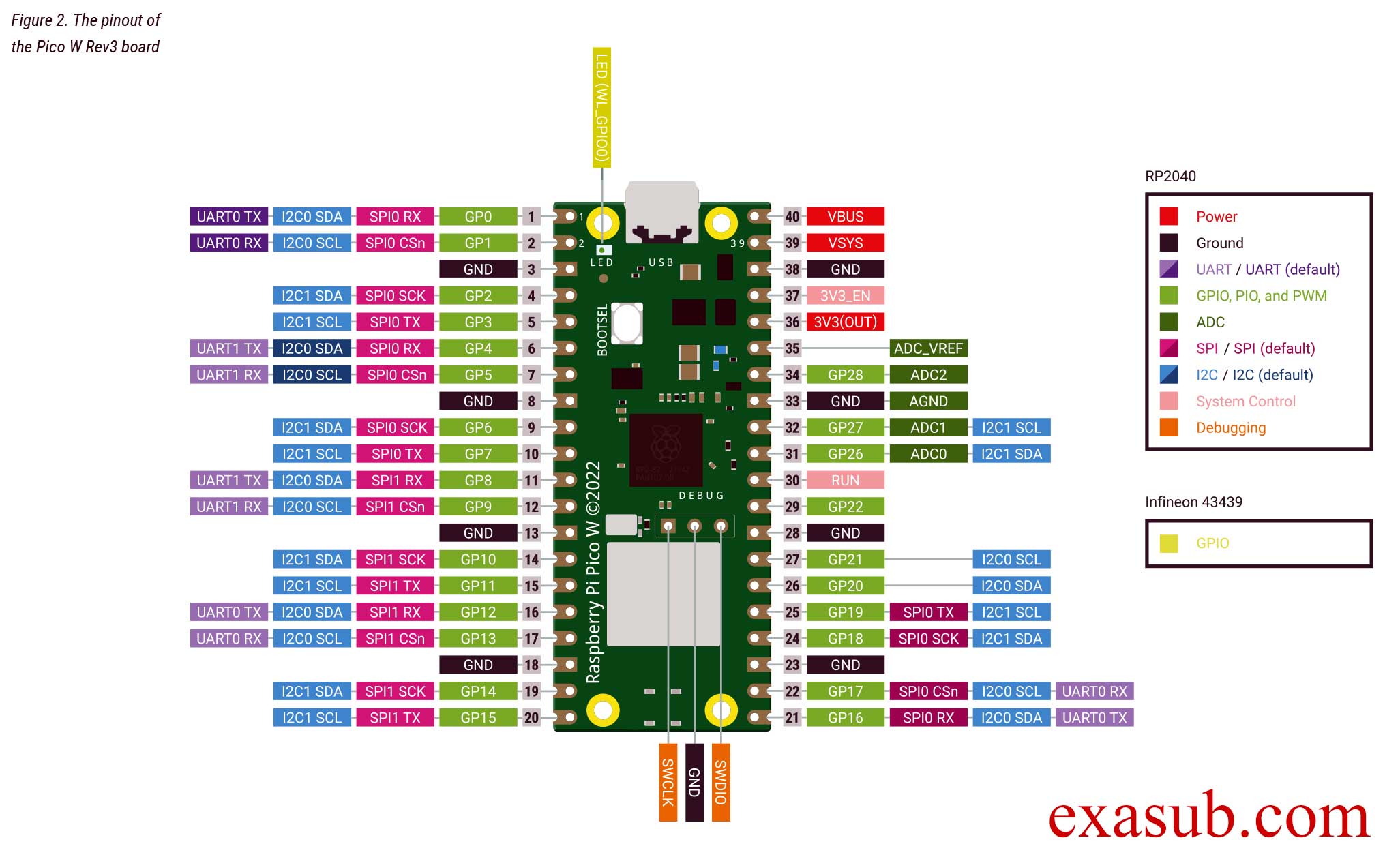
The raspberry pi pico w has a LED on it. This LED is not connected to the GPIO pins of RP2040 microcontroller directly.
As you can see in the image of the pinout taken from the official datasheet. The onboard LED is connected to a pin ‘WL_GPIO0’. WL_GPIO0 is an internal pin.
There are different ways to program the pico W. The easiest method is to install thonny IDE. And install micropython on the pico w.
After you have installed thonny. Now connect you raspberry pi pico w board to the computer USB port while holding the onboard BOOTSEL button. Then follow the steps shown in the following images.
Step 1Step 2Step 3step 4. Click Install after this.
After you have done the above steps. You now have to install a MicroPython library.
picozero is a MicroPython library which has functions for Wifi and other RP2040 chip.
To complete the projects in this path, you need to install the picozero library as a Thonny package.
In Thonny, choose Tools > Manage packages.
Code
import machine
import time

# create a Pin object to control the LED on pin 'WL_GPIO0'
led_pin = machine.Pin('WL_GPIO0', machine.Pin.OUT)

# enter an infinite loop
while True:
    # set the LED pin to a high (on) state
    led_pin.value(1)
    # pause the program for one second
    time.sleep(1)
    # set the LED pin to a low (off) state
    led_pin.value(0)
    # pause the program for one second
    time.sleep(1)
In this program, we first import the machine module and the time module. The machine module provides access to hardware-level features on the Raspberry Pi Pico, while the time module provides functions for time-related operations.
Next, we create a Pin object called led_pin to control the LED connected to the pin labeled ‘WL_GPIO0’. The machine.Pin() function is used to create the led_pin object, with the first argument specifying the pin label and the second argument specifying that the pin is an output pin, i.e. we can set its state to high or low.
Then, we enter an infinite loop using the while True: statement. Within the loop, we use the value() method of the led_pin object to set the state of the LED pin to high (on) or low (off), with a one second delay between each state change using the time.sleep() function.
Comments are added to explain each line of code and make it easier to understand the purpose and function of the program.
Step2: Create a New Workspace A workspace is a directory which will contain all your code and library related to your project.
Step 3: click on “Start new STM32 Project” button
Step 4: Select your board “stm32l476G-DISCO”
Step 5: Give your project a name Do not change any options
Step 6: Select “YES” when prompted for “Initialze all peripheral with their default mode” It is very important that you select YES other wise it will remove all the associated peripherals and you have to manually add the desired peripherals one by one; which is very difficult for beginners.
After these steps your project is created and it will open a STM32 CUBEMX inside your IDE.
Please watch the video. As there are a lots of steps and instruction which are difficult to explain by writing alone. Video will show you a step by step procedure and give you a basic explainition.
You can now change the option or you can proceed forward and click on generate code. This will create all the required code changes.
Now you can open you “main.c” file inside your IDE and write code.