Posted on 1 Comment

How to use MG90S Servo Motor with Raspberry Pi Pico using micropython

I have this MG90S small servo motor. It is supposed to go from 0° to 180°.

Because of their low cost, they have a short range which is less than 180°. Some go to 135°, 100° or 150°.

PWM signal required by servo to move.

Frequency = 50Hz
Time Period = 0.02 Second or 20 mili second
Pulse width range: 500us to 2500us

Properties of pulse width
At 500us pulse width the servo position will be 0°
At 2500us pulse width the servo position will be 180°

It is a good habit to check the servo controls before putting it in a project and make the adjustments in code or in hardware.

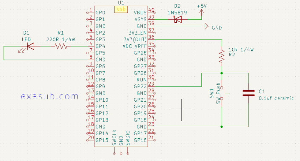
Hardware Connections

Raspberry Pi PicoServo Motor
GNDGND (Brown color wire)
VsysVCC (Red color wire)
GP9Signal (Orange color wire)

Most small and micro Servo operate from 5V to 6V.
If a servo is designed to operate at 3.3V always check it’s datasheet carefully.

Calculations

Raspberry pi pico has a 16 bit PWM controller.
This means we set its frequency to 50Hz by
pwm.freq(50)
This means that one oscillation has 65535 steps

65535 steps = 20 ms

First we convert angles to pulse width time

pulse width = angle/90 + 0.5
then we convert pulse width to step count

steps count = ( 65535 * pulse width ) / 20

Code

import machine
import utime

Led_pin = 25
LED = machine.Pin(Led_pin, machine.Pin.OUT)

# Configure the GPIO pin for PWM
pwm_pin = machine.Pin(9)
pwm = machine.PWM(pwm_pin)

# Set the PWM frequency to 50 kHz
pwm.freq(50)

# Debug Message Print
debug = 0

time_delay = 1/10
increment_step = 100
decrement_step = -200

'''
# Function: deg_to_time
# Parameters: deg : degree (0 - 180)
# Description: This function takes the degree and translates them
                to Pulse Width time.
                For a servo motor we have to use a pulse width of 500us to 2500us

'''
def deg_to_time(deg):
    temp = ((deg/90)+0.5)
    if debug:print("deg ",deg," to timems: ",temp)
    return temp

'''
# Function: timems_to_duty
# Parameters: timems : pulse width time in milli second
# Description: This function takes pulse width duration of 500us to 2500us.
                and generates a duty cycle value.

'''
def timems_to_duty(timems):
    temp = 20/timems
    temp1 = 65535/temp
    if debug:print("timems to duty: ",temp1)
    return temp1

'''
# Function: set_pwm
# Parameters: duty : duty cycle value (0 - 65535)
# Description: This function takes a duty cycle value and set it for the PWM.

'''
def set_pwm(duty):
    pwm.duty_u16(int(duty))
    if debug:print("duty cycle: ",duty)
    
def angle_to_pwm(angle):
    set_pwm(int(timems_to_duty(deg_to_time(angle))))


while(1):
        # sweep from 0  to 180
    for _ in range(0,180,1):
        angle_to_pwm(_)
        utime.sleep(time_delay)
        # sweep from 180  to 0
    for _ in range(180,0,-1):
        angle_to_pwm(_)
        utime.sleep(time_delay)
Posted on Leave a comment

How to Use C SDK to Create UF2 file which Interface Ultrasonic Sensor with Raspberry Pi Pico

Hardware setup

HC-SR04Raspberry Pi Pico
VCCVSYS
GNDGND
TrigGP2
ECHOGP3

I am using raspberry pi model 3 b+ for the code compilation.

  1. Create the folder named “distance” inside the pico folder
  1. Then Create the test.c and CMakeLists.txt files using touch command.
touch test.c CMakeLists.txt
  1. Copy the pico_sdk_import.cmake file from pico/pico-sdk/external
  2. make the build directory using mkdir command
mkdir build
  1. Here is the CMakeLists.txt code
# Set the minimum required version of CMake
cmake_minimum_required(VERSION 3.13)

# Import the Pico SDK CMake configuration file
include(pico_sdk_import.cmake)

# Set the project name and languages
project(test_project C CXX ASM)

# Set the C and C++ language standards
set(CMAKE_C_STANDARD 11)
set(CMAKE_CXX_STANDARD 17)

# Initialize the Pico SDK
pico_sdk_init()

# Create an executable target called "test" from the source file "test.c"
add_executable(test
    test.c
)

# Enable USB stdio for the "test" target (used for serial communication)
pico_enable_stdio_usb(test 1)

# Disable UART stdio for the "test" target
pico_enable_stdio_uart(test 0)

# Add extra outputs for the "test" target (e.g., UF2 file)
pico_add_extra_outputs(test)

# Link the "test" target with the pico_stdlib library
target_link_libraries(test pico_stdlib)
  1. Here is the c code that you put inside the test.c file
#include <stdio.h>
#include "pico/stdlib.h"
#include "hardware/gpio.h"
#include "hardware/timer.h"

#define TRIG_PIN 2
#define ECHO_PIN 3

float measure_distance() {
    gpio_put(TRIG_PIN, 1);
    sleep_us(10);
    gpio_put(TRIG_PIN, 0);

    uint32_t start_ticks = 0;
    uint32_t end_ticks = 0;

    while (gpio_get(ECHO_PIN) == 0) {
        start_ticks = time_us_32();
    }

    while (gpio_get(ECHO_PIN) == 1) {
        end_ticks = time_us_32();
    }

    uint32_t elapsed_time_us = end_ticks - start_ticks;
    float distance_cm = elapsed_time_us * 0.0343 / 2;

    return distance_cm;
}

int main() {
    stdio_init_all();
    sleep_ms(2000);  // Wait for sensor to stabilize

    gpio_init(TRIG_PIN);
    gpio_set_dir(TRIG_PIN, GPIO_OUT);

    gpio_init(ECHO_PIN);
    gpio_set_dir(ECHO_PIN, GPIO_IN);

    while (1) {
        float distance = measure_distance();
        printf("Distance: %.2f cm\n", distance);
        sleep_ms(1000);
    }

    return 0;
}
  1. after this you need to execute this line of code in the terminal
export PICO_SDK_PATH=../../pico
  1. then execute the following code in the given order
cd build
cmake ..
make

If everything worked, you will have your ulf2 file in your build directory

Posted on Leave a comment

Interfacing a 5V Ultrasonic Sensor with 3.3V GPIO of Raspberry Pi Pico: A Voltage Divider Solution

I have an old HC-Sr04 ultrasonic sensor. I don’t know if it’s GPIO voltage compatible with the 3.3V microcontroller.
On the internet, I found that the old sensors work with 5V.

So, I used a voltage divider made of 1K ohm and 1.5K ohm Surface mount resistors. To bring down the 5V to a suitable 3V.

I want to reduce the voltage level on the ECHO pin of the ultrasonic sensor to a safe level for the Raspberry Pi Pico’s GPIO pins. Let’s assume we have chosen resistors R1 and R2 with values of 1K and 1.5K, respectively.

You can also use the voltage divider calculator for this
Voltage Divider Calculator

Using the voltage divider formula, we can calculate the output voltage at the midpoint (E_3) of the voltage divider circuit:

V_out = V_in * (R2 / (R1 + R2))

Since the Vsys pin of the Raspberry Pi Pico provides a voltage of 5V, we can calculate the output voltage:

V_out = 5V * (1.5K / (1K + 1.5K))
= 5V * (1.5K / 2.5K)
= 5V * 0.6
= 3V

With the given resistor values, the output voltage at the midpoint of the voltage divider circuit will be 3V. This 3V output is within the safe voltage range for the GPIO pins of the Raspberry Pi Pico.

Code Implementation:

To implement the interface between the ultrasonic sensor and the Raspberry Pi Pico, we will utilize MicroPython, a lightweight Python implementation for microcontrollers. The following code snippet demonstrates the necessary steps:

from machine import Pin
import utime
trigger = Pin(2, Pin.OUT)
echo = Pin(3, Pin.IN)
def ultra():
   trigger.low()
   utime.sleep_us(2)
   trigger.high()
   utime.sleep_us(10)
   trigger.low()
   while echo.value() == 0:
       signaloff = utime.ticks_us()
   while echo.value() == 1:
       signalon = utime.ticks_us()
   timepassed = signalon - signaloff
   distance = (timepassed * 0.0343) / 2
   print("The distance from object is ",distance,"cm")
   
while True:
   ultra()
   utime.sleep(1)
Posted on Leave a comment

Raspberry Pi Pico Internal Temperature Sensor Based Fan Speed Control using PID Algorithm with Anti-Windup Logic

This system uses the Raspberry pi pico development board which has an RP2040 microcontroller. The RP2040 microcontroller has an internal temperature sensor.

Using its internal temperature sensor I have devised a very simple setup that demonstrates the PID algorithm. Using PID Algorithm control technique I am controlling the fan speed by changing the PWM duty cycle.

Component required:

  1. Raspberry Pi Pico
  2. PC Fan (+12V)
  3. L298n Module
  4. +12V Power supply

Commonly the PC fan changes its speed by PWM signal, I am sending a PWM signal of frequency 29Khz. Most PC fans operate from 25Khz to 30Khz. PWM signal duty cycle can be from 30% to 100%. At duty cycle lower than 30% PC fan won’t start.

We will dive into the code and explain each step of the implementation.

Code Overview:
The code provided is written in MicroPython and utilizes the machine module for hardware interactions. Here’s an overview of the key components and functionalities:

  1. PWM Configuration: The code configures a GPIO pin for Pulse Width Modulation (PWM) and sets the frequency to 29 kHz. PWM is used to control the speed of the fan.
  2. Temperature Sensor Configuration: The internal temperature sensor is configured using the ADC (Analog-to-Digital Converter) module. The conversion factor is calculated to convert the raw ADC readings to temperature values.
  3. PID Algorithm Implementation: The PID algorithm is implemented using proportional (P), integral (I), and derivative (D) control constants. The target temperature is set, and the error between the target temperature and the measured temperature is calculated. The code calculates the proportional, integral, and derivative terms and combines them to obtain the PID value.
  4. Anti-Windup Logic: To prevent windup issues, an anti-windup logic is implemented. It limits the PID value within a valid range to avoid saturation or unstable behavior.
  5. Timer Interrupts: Timer objects are created to trigger callback functions at regular intervals. The 100 ms timer callback updates the PID value and adjusts the fan speed accordingly, while the 1-second timer callback prints relevant information for monitoring and debugging purposes.

Implementation Walkthrough:

  1. PWM and Temperature Sensor Configuration: The code starts by configuring the PWM pin and the internal temperature sensor.
  2. PID Constants and Variables: The proportional control constant (kp), minimum duty cycle value (min_duty_cycle), and target temperature (target_temp) are set. Variables for duty cycle, error, temperature, integral error (i_err), integral count (i_cnt), derivative count (d_cnt), previous error (prev_err), and PID value (PID) are initialized.
  3. Timer Interrupts: Timer objects are created and initialized to trigger the respective callback functions every 100 ms and 1 second.
  4. PID Calculation and Fan Control: In the timer callback function for 100 ms, the raw temperature is converted to a temperature value. The error, integral error, derivative count, proportional count, and PID value are calculated. The PID value is limited to a valid range and converted to an appropriate duty cycle value for the PWM. The duty cycle is applied to control the fan speed.
  5. Monitoring and Debugging: The timer callback function for 1 second prints relevant information such as the PID value, error, duty cycle, temperature, derivative count, integral count, and proportional count.
import machine
import utime

# Configure the GPIO pin for PWM
pwm_pin = machine.Pin(9)
pwm = machine.PWM(pwm_pin)

# Set the PWM frequency to 29 kHz
pwm.freq(29000)

# Configure the internal temperature sensor
sensor_temp = machine.ADC(machine.ADC.CORE_TEMP)
conversion_factor = 3.3 / 65535

# Set the proportional control constants
#target_temp = 25  # Set the desired target temperature
# Set the proportional control constants
#target_temp = 25.63997  # Set the desired target temperature
target_temp = 25.17182  # Set the desired target temperature
#target_temp = 24.70368
#target_temp = 24.23554
#target_temp = 23.76739
#target_temp = 23.29925
kp = (((2**16)-1) * -1)
min_duty_cycle = (((2**16)-1) * 0.3)  # Minimum duty cycle value to start the fan

duty_cycle = 0
error = 0
temperature = 0

# Initialize the timestamp for 1 second intervals
timestamp_1s = utime.time()
p_cnt = 0
i_err = 0
Ki = -200
i_cnt = 0

prev_err = 0
Kd = -2500
d_cnt = 0
PID = 0
# Timer interrupt callback function for 100 ms interval
def timer_callback_100ms(timer):
    global duty_cycle, error, temperature,i_err,i_cnt,prev_err,Kd,d_cnt,p_cnt,PID,Ki

    raw_temp = sensor_temp.read_u16() * conversion_factor
    temperature = (27 - (raw_temp - 0.706) / 0.001721)
    error = target_temp - temperature
    i_err += (error)
    i_cnt = int(i_err * Ki)
    d_cnt = ((error - prev_err) * Kd)/0.1
    p_cnt = error * kp
    PID = (p_cnt + d_cnt + i_cnt)
    if PID >= 65535:
        PID = 65535
    if PID <= 0 :
        PID = 0
    duty_cycle = int(PID)
    
    pwm.duty_u16(duty_cycle)
    '''
    if error >= 0:
        #duty_cycle = max((duty_cycle - int(error * kp)), 0)
        duty_cycle = int(max(( d_cnt + i_cnt + (1 * error * kp)), 0))
        if duty_cycle <= 0:
            duty_cycle = 0
        pwm.duty_u16(duty_cycle)
    elif error < 0:
        duty_cycle = int(min( d_cnt + i_cnt +  error * kp), 65535))
        
        #duty_cycle = min(max((duty_cycle + int(-1 * error * kp)), int(min_duty_cycle)), 65535)
        pwm.duty_u16(int(duty_cycle))
    '''
    prev_err = error

# Timer interrupt callback function for 1 second interval
def timer_callback_1s(timer):
    print(f"pid: {PID}\terror: {error}\tduty: {duty_cycle}\tTemp: {temperature}\td_cnt: {d_cnt}\ti_cnt: {i_cnt}\tp_cnt: {p_cnt}")

# Create timer objects
timer_100ms = machine.Timer()
timer_1s = machine.Timer()

# Configure the timer to trigger the 100 ms callback function every 100 milliseconds
timer_100ms.init(period=100, mode=machine.Timer.PERIODIC, callback=timer_callback_100ms)

# Configure the timer to trigger the 1 second callback function every 1 second
timer_1s.init(period=1000, mode=machine.Timer.PERIODIC, callback=timer_callback_1s)

# Main loop
while True:
    # Add any other desired non-blocking operations here
    
    # Sleep briefly to avoid excessive CPU usage
    utime.sleep(0.01)

Posted on Leave a comment

How to use Neo 6m GPS Module with Raspberry Pi Pico

Connect the GPS module to the Raspberry Pi Pico as follows:

  1. Connect the VCC pin of the GPS module to the 3.3V pin on the Pico.
  2. Connect the GND pin of the GPS module to the GND pin on the Pico.
  3. Connect the TX pin of the GPS module to any GPIO pin1 on the Pico
  4. Connect the RX pin of the GPS module to any GPIO pin0 on the Pico

Note: Since Raspberry Pi Pico operates at 3.3V logic level, you can directly connect the GPS module without voltage level shifting.

The module will output something like this

$GPRMC,103255.00,V,,,,,,,180523,,,N*70
$GPVTG,,,,,,,,,N*30
$GPGGA,103255.00,,,,,0,00,99.99,,,,,,*66
$GPGSA,A,1,,,,,,,,,,,,,99.99,99.99,99.99*30
$GPGSV,1,1,01,18,,,31*73
$GPGLL,,,,,103255.00,V,N*4A

These are the NMEA messages. by decoding these messages we get our data.

You can read about them at http://aprs.gids.nl/nmea/
   $GPGGA - Global Positioning System Fix Data
   $GPGLL - Geographic position, latitude / longitude
   $GPGSA - GPS DOP and active satellites 
   $GPGSV - GPS Satellites in view
   $GPRMC - Recommended minimum specific GPS/Transit data
   $GPVTG - Track made good and ground speed

Micropython Code

import machine
import utime

# UART configuration
uart = machine.UART(0, baudrate=9600, tx=machine.Pin(0), rx=machine.Pin(1))
date = ""
time = ""
altitude = ""
course = ""
speed = ""
sats = ""
hdop = ""
latitude = ""
latitude_dir = ""
latitude_decimal =""
longitude = ""
longitude_dir = ""
longitude_decimal = ""
fix = ""


def dms_to_decimal(degrees, minutes, seconds):
    degrees = int(degrees)
    minutes = int(minutes)
    seconds = float(seconds)
    decimal = degrees + (minutes / 60) + (seconds / 3600)
    return decimal

while True:
    
    if uart.any():
        data = uart.readline()
        if data:
            try:
                # Decode the GPS data
                data_str = data.decode('utf-8').strip()
                
                if data_str.startswith('$GPRMC'):
                    values = data_str.split(',')
                    
                    if len(values) == 13:
                        date = values[9][0:2] + '/' + values[9][2:4] + '/' + values[9][4:]
                    #print(date)
                        
                if data_str.startswith('$GPVTG'):
                    values = data_str.split(',')
                    if len(values) >= 9:
                        #print(values)
                        course = values[1]  # Course over ground
                        speed = values[7]   # Speed over ground
                        
                        
                if data_str.startswith('$GPGGA'):
                    # Split the data string into individual values
                    values = data_str.split(',')
                    
                    #print(values)
                    if len(values) >= 15:
                        # Extract the required values
                        sats = values[7] if values[7] else ''  # Number of satellites
                        hdop = values[8] if values[8] else ''  # HDOP
                        latitude = values[2][:2] + '°' + values[2][2:4] + "'" + values[2][4:] + '"' + values[3]  # Latitude
                        latitude_dir = values[3]
                        longitude = values[4][:3] + '°' + values[4][3:5] + "'" + values[4][5:] + '"' + values[5]  # Longitude
                        longitude_dir = values[5]
                        latitude_decimal = dms_to_decimal((values[2][:2]),(values[2][2:4]),(values[2][4:]))
                        longitude_decimal = dms_to_decimal(values[4][:3],values[4][3:5],values[4][5:])
                        fix = values[6] if values[6] else ''  # Fix status
                        time = values[1][0:2] + ':' + values[1][2:4] + ':' + values[1][4:6]  # Time
                        altitude = values[9] if values[9] else ''  # Altitude


            except UnicodeError:
                pass

    utime.sleep(0.1)
    # Print the data
    
    print(f"Sats: {sats} HDOP: {hdop}")
    print("Latitude:", latitude)
    print("Longitude:", longitude)
    print(f"Latitude: {latitude_decimal} {latitude_dir} \t Longitude: {longitude_decimal} {longitude_dir}")
    print("Fix:", fix)
    print(f"Time: {time} Date: {date}")
    print(f"Altitude: {altitude}\n")
    # Print the GPVTG data
    print(f"GPVTG: Course: {course} Speed:{speed} km/h")
    

Output

GPVTG: Course: 49.43 Speed:2.164 km/h
Sats: 06 HDOP: 1.39
Latitude: 28°36'.51385"N
Longitude: 077°03'.89436"E
Latitude: 28.60014 N 	 Longitude: 77.05025 E
Fix: 1
Time: 14:24:37 Date: 18/05/23
Altitude: 216.4
Posted on Leave a comment

Interfacing an external +5V power supply with Raspberry Pi Pico

From the section 4.5 Powering Pico of the official Raspberry Pi Datasheet. I have decided to use the first method which is suggest to use a schottky diode with the VSYS pin.

I have used 1N5819 Schottky diode.which has
VRRM = 40V,
Maximum average forward rectified current IF(AV) = 1A

The schottky diode and the diode on the Pico PCB makes a power OR-ring. In this system the pico will take power which is greater. So if the power is greater from USB it will take power from USB. and if the voltage is greater from the power supply it will take power from it. Because of the use of schottky diode there will be a diode drop. To reduce it you can use a P-MOS as suggested in the datasheet. But for simpler circuits the Schottky diode works.

Using the suggestion from the datasheet. I made a schematic in KiCad.

The 1N5819 schottky connects to a custom switching step down voltage regulator made using the MC34063A IC.

This is the micropython program code that i used

import machine
import time

# Set up the button on GPIO22 with external pull-up resistor
button = machine.Pin(22, machine.Pin.IN, machine.Pin.PULL_UP)

# Set up the LED
LED = machine.Pin(4, machine.Pin.OUT)

# Set up debounce delay
debounce_delay = 50

# Initialize previous button value
prev_button = 1

# Loop forever
while True:
    # Read the current button value
    curr_button = button.value()

    # If the button is pressed, print a message
    if curr_button == 0 and prev_button == 1:
        print("Button pressed!")
        # Wait for a short delay to debounce
        time.sleep_ms(debounce_delay)
        #toggle the LED
        LED.value(not LED.value())

    # Update the previous button value
    prev_button = curr_button

Posted on Leave a comment

How to use button with Raspberry Pi Pico using micropython

The Pico has internal pull up /down circuits inside it.

I have made this simple circuit for demonstration.

Schematic showing LED connected to GP4 and a Button connected to GP22

Button could be connected in two ways.

  1. Internal Pull Up/Down
  2. External Pull UP/Down

In the schematic i connected a button to GP22 using a external pull up of resistor 10k. I also used a capacitor in parallel with the button to debounce the button externally.

Using a external pull-up resistor can also help to protect the GPIO pin from damage due to excessive current flow. Without a pull-up resistor, a short circuit or other electrical fault in the switch or button could potentially allow a large current to flow through the GPIO pin, damaging it or the microcontroller itself.

Sample Code

import machine

# Set up the button on GPIO22 with external pull-up resistor
button = machine.Pin(22, machine.Pin.IN, machine.Pin.PULL_UP)

# Set up the LED on GPIO4
led = machine.Pin(4, machine.Pin.OUT)

# Loop forever
while True:
    # Read the current button value
    curr_button = button.value()

    # If the button is pressed, turn on the LED
    if curr_button == 0:
        led.value(1)
    # Otherwise, turn off the LED
    else:
        led.value(0)

Posted on Leave a comment

How to use GPIO of Raspberry Pi Pico as Output Pins

One of the most important features of the Raspberry Pi Pico is its General-Purpose Input/Output (GPIO) pins. These pins can be used to control external devices, such as LEDs, motors, and relays.

The Raspberry Pi Pico has 26 GPIO pins, numbered from GP0 to GP25.
Each pin can be individually programmed to perform a specific task.

Steps to Use GPIO as Output Pins

To use the GPIO pins of Raspberry Pi Pico as output pins, follow these steps:

Step 1: Set up your Raspberry Pi Pico board and connect it to your computer via USB.

You can make the KiCad project like following.
Connect a LED via a 220 ohm resistor to the GP4 pins.

You can download and use the symbol and footprint from link below

Raspberry Pi Pico Symbol in KiCad 7 Project Library

To calculate the value of resistor you can use the Ohm’s Law Calculator
Use the following values
V (voltage): 3.3
A (Current) : 0.015
when you press calculate it will give you a resistance value of 220 ohm.

Remember never exceed the current value of 0.015A or 15mA for small leds as higher current may damage the component.

Schematic Diagram Showing LED connected to GP4 Pin via a 220 ohm resistor.

Step 2: Open your preferred code editor and create a new Python script.

Step 3: Import the required libraries by adding the following lines of code at the beginning of your script:

import machine
import utime

The “machine” library provides access to the GPIO pins of Raspberry Pi Pico, and the “utime” library allows us to add delays in our code.

Step 4: Define the pin number you want to use as an output pin. For example, if you want to use GP5 as an output pin, add the following line of code:

led_pin = machine.Pin(4, machine.Pin.OUT)

Here, we are using the “machine.Pin” class to define the pin number (4) as an output pin.

Step 5: Turn on the LED by setting the output value of the pin to 1. Add the following line of code:

led_pin.value(1)

This will set the output value of the GP4 pin to 1, which will turn on the LED connected to it.

Step 6: Add a delay in your code to keep the LED on for a specific time. For example, if you want to keep the LED on for 2 seconds, add the following line of code:

utime.sleep(2)

This will add a 2-second delay in your code.

Step 7: Turn off the LED by setting the output value of the pin to 0. Add the following line of code:

led_pin.value(0)

This will set the output value of the GP4 pin to 0, which will turn off the LED connected to it.

Step 8: Save your code and run it on your Raspberry Pi Pico board. You should see the LED turn on for 2 seconds and then turn off.

Complete Code

import machine
import utime

led_pin = machine.Pin(4, machine.Pin.OUT)

led_pin.value(1)

utime.sleep(2)

led_pin.value(0)

Example Code to try

import machine
import time

led_pin = machine.Pin(4, machine.Pin.OUT)

led_pin.value(1)  # turn on the LED
time.sleep(1)     # wait for a second
led_pin.value(0)  # turn off the LED
time.sleep(1)     # wait for a second

for i in range(10):
    led_pin.value(1)  # turn on the LED
    time.sleep(0.5)   # wait for half a second
    led_pin.value(0)  # turn off the LED
    time.sleep(0.5)   # wait for half a second
Posted on 1 Comment

Raspberry Pi Pico Symbol in KiCad 7 Project Library

This project has all the files necessary to make a project using it.

In this project i have included a symbol library and a footprint library. It is a custom library. You can use this in another project by adding it into the project library list.

This project is made using the KiCad 7.

Symbol library name : RP2040_parts.kicad_sym

Footprint library name: Library.pretty

This project also has the 3d STEP file in it.

Posted on Leave a comment

Handling errors with strings in MicroPython on Raspberry Pi Pico

When working with strings in MicroPython on Raspberry Pi Pico, it is important to handle errors that may occur during string operations. Errors can occur for a variety of reasons, such as invalid input or incorrect syntax. Fortunately, MicroPython provides several built-in mechanisms for handling errors with strings.

One of the most common errors that can occur with strings is a ValueError due to incorrect formatting. For example, if you try to convert a string to a numeric type and the string is not a valid number, a ValueError will be raised. To handle this error, you can use a tryexcept block:

string = "abc123"
try:
    num = int(string)
    print(num)
except ValueError:
    print("Invalid input, cannot convert to int.")

In this example, the int() function attempts to convert the string "abc123" to an integer. However, since "abc123" is not a valid integer, a ValueError is raised. The tryexcept block catches the error and prints a helpful message.

Another common error that can occur with strings is an IndexError due to attempting to access an element that does not exist in a string. For example, if you try to access the 10th character of a string that only has 5 characters, an IndexError will be raised. To handle this error, you can use a similar tryexcept block:

string = "hello"
try:
    char = string[10]
    print(char)
except IndexError:
    print("Index out of range, cannot access character.")

In this example, we attempt to access the 10th character of the string "hello", which does not exist. An IndexError is raised, and the tryexcept block catches the error and prints a helpful message.

It is also possible to raise your own custom errors when working with strings. For example, you may want to raise an error if a string does not meet certain criteria. To do this, you can use the raise statement:

def process_string(string):
    if len(string) < 5:
        raise ValueError("String must be at least 5 characters long.")
    # do something with the string

In this example, the process_string() function raises a ValueError if the input string is less than 5 characters long. This allows the function to provide useful feedback to the user if the input is invalid.

In summary, handling errors with strings in MicroPython on Raspberry Pi Pico involves using tryexcept blocks to catch built-in errors, and raising your own custom errors when necessary. By using these mechanisms, you can ensure that your code is robust and handles unexpected situations gracefully.