Posted on Leave a comment

Interfacing an external +5V power supply with Raspberry Pi Pico

From the section 4.5 Powering Pico of the official Raspberry Pi Datasheet. I have decided to use the first method which is suggest to use a schottky diode with the VSYS pin.

I have used 1N5819 Schottky diode.which has
VRRM = 40V,
Maximum average forward rectified current IF(AV) = 1A

The schottky diode and the diode on the Pico PCB makes a power OR-ring. In this system the pico will take power which is greater. So if the power is greater from USB it will take power from USB. and if the voltage is greater from the power supply it will take power from it. Because of the use of schottky diode there will be a diode drop. To reduce it you can use a P-MOS as suggested in the datasheet. But for simpler circuits the Schottky diode works.

Using the suggestion from the datasheet. I made a schematic in KiCad.

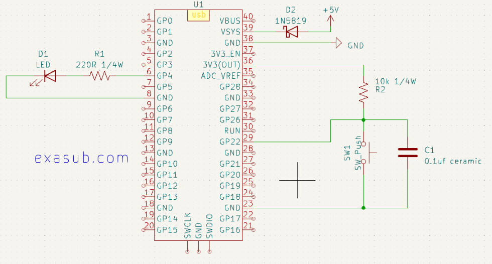
The 1N5819 schottky connects to a custom switching step down voltage regulator made using the MC34063A IC.

This is the micropython program code that i used

import machine
import time

# Set up the button on GPIO22 with external pull-up resistor
button = machine.Pin(22, machine.Pin.IN, machine.Pin.PULL_UP)

# Set up the LED
LED = machine.Pin(4, machine.Pin.OUT)

# Set up debounce delay
debounce_delay = 50

# Initialize previous button value
prev_button = 1

# Loop forever
while True:
    # Read the current button value
    curr_button = button.value()

    # If the button is pressed, print a message
    if curr_button == 0 and prev_button == 1:
        print("Button pressed!")
        # Wait for a short delay to debounce
        time.sleep_ms(debounce_delay)
        #toggle the LED
        LED.value(not LED.value())

    # Update the previous button value
    prev_button = curr_button

Posted on Leave a comment

15V Unregulated DC Power Supply using 12Vrms step-down transformer

There are two ways to make DC power supply

  1. Linear
  2. Switching

Linear Power Supply
Continous control of voltage is done at any instance of time. It uses a pass transistor with an error amplifier to regulate the voltage supply.
example: 7805, 7905, LM317 etc

Switching Power Supply
It also uses the pass transistor along with an inductor and a capacitor to store the energy and release the energy. By controlling the switching of the pass transistor, the Voltage is regulated. It is more complex than the linear power supply.
The advantage of switching is that the transformer size gets reduced. Which reduced the cost of the power supply. The Reduced size also reduced the weight; which further increases the portability of the power supply.

[ A C Mains ] -> [StepDown Transformer] -> [Bridge Rectifier] -> [Filter] -> [Unregulated DC]

I am using a step-down transformer. Which transformer 220V 50Hz AC to 12 Vrms AC.

The Vrms is converted to Vdc which is dc equivalent voltage.

So, 12 Vrms = 12 x 1.414 Vdc

= 16.968 (approx.) Vdc

this Vdc is passed through the bridge rectifier which drops 1.5V to 1.8V

= 16.968 – 1.8

= 15.168 V

which is then filtered through the Capacitor filter

C = ( I x t ) / V

I is the amount of current passing through the capacitor at maximum load.

Let I = 1A

t is the ripple time which is taken 10 mS if using 50Hz cycles.

C = [1 x 10 x 10^(-3) ] / 15.168

= 6.59 x 10^(-4) F

= 659 micro Frad

So we will use a standard capacitor that is either equal to or bigger than the above value i.e 1000uF will OK.